


Overview
What is Zero Liquid Discharge?
Zero Liquid Discharge (ZLD) is a wastewater treatment architecture in which no liquid effluent leaves the plant boundary — water is recovered for reuse and the residual brine is evaporated to solid salt. SRPEPL designs, builds and operates ZLD plants for power, steel, textile, pharma, chemical and FMCG industries across India, with executed capacities from small industrial streams to 2.64 MLD integrated-steel-plant trains.
Our approach is membrane-first: segregate streams, stabilise chemistry, recover 85–95% of water through UF, RO, HPRO and DTRO before any thermal stage — then concentrate only the irrecoverable brine in MEE, MVR or ATFD. The result is a smaller evaporator, lower electrical and steam demand, and a ZLD plant that holds performance through its defect liability period and beyond.
Root Cause Analysis
Why do ZLD plants fail to hit zero discharge?
Most underperforming ZLD plants in India fail for the same three reasons: streams are mixed too early, recovery potential is ignored, and the evaporator is overloaded.
When effluent streams with different chemistries are combined before treatment, pretreatment cannot stabilise the mix, RO recovery stays low, and the bulk of the hydraulic load ends up in the thermal stage — where energy consumption is 10–30× higher per m³ than membrane filtration.
Context
Where ZLD sits in the treatment hierarchy
ZLD is different from tertiary treatment because it changes the plant boundary — instead of discharging treated effluent, the plant discharges nothing liquid.
Architecture
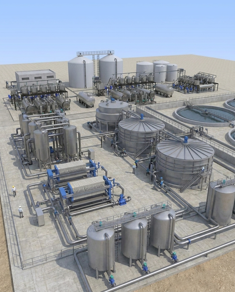
The membrane-first ZLD process
Because membrane filtration consumes 0.8–6 kWh/m³ and evaporation consumes 20–120 kWh/m³, every cubic metre pushed through a membrane instead of boiled saves 4–30× in energy. The architecture below reflects this logic.
Energy
How much energy does ZLD consume?
Energy consumption in industrial ZLD varies by an order of magnitude depending on where the water is recovered. Pushing water through a membrane is always cheaper than boiling it.
Thermal Stage Selection
MEE vs MVR — which is right?
MVR compresses the vapour from evaporation, raises its temperature and reuses it as the heating medium — replacing external steam with electrical energy. It works best when the feed stream is stable, silica is below 150–200 ppm, hardness is controlled upstream, and flow variation is under ±15%.
MEE is preferred where steam is already available and cheap, where feed silica exceeds 200 ppm, feed chemistry is variable, or flow is too low to justify the compressor capital cost of MVR. SRPEPL supplies both configurations.
| Decision driver | Choose MVR when | Choose MEE when |
|---|---|---|
| Energy source | Electricity available; no cheap steam | Captive steam or waste heat available |
| Feed silica | <150 ppm; hardness pre-controlled | >200 ppm; variable chemistry |
| Flow stability | Variation <±15% | Flow varies widely |
| Flow rate | Mid-to-large (>5 m³/hr brine) | Small to large; any range |
| Payback | 2–4 yr vs MEE on electricity-cheap sites | Immediate when steam is effectively free |
Engineering
Key design parameters
ZLD plant economics are driven by six variables: feed TDS, feed chemistry variability, target recovery, silica and hardness profile, available utilities, and disposal route for recovered salt. A site-specific water-balance model — built from actual 12-month influent analysis — determines the optimal membrane-thermal split.
| Parameter | Typical range | What it drives |
|---|---|---|
| Feed TDS | 3,000–40,000 mg/L | Membrane selection, number of RO stages, energy cost |
| Feed silica | 20–400 mg/L | Antiscalant selection, RO recovery ceiling, DTRO decision |
| Feed hardness | 100–2,000 mg/L (as CaCO₃) | Softening requirement, scaling risk |
| RO recovery (first pass) | 70–80% | Number of passes, antiscalant dosing |
| HPRO/DTRO recovery | 40–65% on RO reject | Overall train recovery, evaporator sizing |
| Overall water recovery | 85–99% | Evaporator size, OPEX, land area |
| Salt purity (if recovered) | 90–98% w/w | Crystalliser vs ATFD selection |
Executed Projects
ZLD track record
Anchor references across Indian steel and power — with a wider installed base of ZLD systems in textile, chemical, pharma and FMCG applications.
 Commissioned
SAIL Bokaro Steel Plant — ZLD Complex
3-stage membrane plus evaporation ZLD recovering process water from steel-plant effluent — one of the anchor ZLD references in India's integrated steel sector. Zero liquid discharge to the Damodar river.
 Under Execution
660 MW × 2 Supercritical Thermal Power Plant
Membrane-based tertiary recycle and ZLD polishing for a 1,320 MW supercritical plant — engineered to cut fresh-water intake while meeting CEA statutory ZLD norms for thermal power stations.
What's Included
SRPEPL's ZLD EPC scope
Single-point turnkey EPC responsibility — from process design through long-term O&M.
Differentiators
Why choose SRPEPL for a ZLD project?
SRPEPL is selected for ZLD projects where the membrane train is the critical technical decision, the feed sits outside standard RO pressure envelopes, or fabrication quality on the pressure side determines whether the plant runs through its performance guarantee.
Existing Plants
Can SRPEPL retrofit an underperforming ZLD plant?
Yes. The typical engagement begins with a site audit — feed analysis, unit-by-unit performance measurement, energy accounting, chemical consumption review — against the plant's original design basis. The most common findings: single-pass RO where two-pass was required, missing HPRO/DTRO stage, silica uncontrolled upstream of MEE, and streams mixed before pretreatment.
Applications
Industries that require ZLD in India
ZLD is mandated or effectively required across several Indian industrial sectors under CPCB and state PCB directives. SRPEPL has designed ZLD plants for power, steel, textile, pharma, chemical, FMCG and electronics applications.
FAQ
Frequently Asked Questions
ZLD is a wastewater treatment architecture in which no liquid effluent leaves the plant boundary. All water is recovered for internal reuse and the residual brine is concentrated to solid salt. A properly designed ZLD plant recovers 95–99% of its influent through pretreatment, membrane filtration (UF, RO, HPRO or DTRO) and thermal evaporation (MEE, MVR or ATFD).
Under CPCB and state PCB directives, ZLD is mandated or effectively required for textile processing CETPs in water-stressed zones, distilleries, tanneries, pharma API manufacturers, thermal power stations under CEA norms, integrated steel plants discharging into protected river basins, and specific chemical process industries. State-level notifications in Haryana, Punjab, Tamil Nadu, Gujarat, Maharashtra and Madhya Pradesh have extended ZLD applicability further.
Indian industrial ZLD CAPEX typically ranges from ₹15–40 Cr per MLD of influent, driven by feed TDS, silica load, civil scope and the MEE vs MVR choice. OPEX ranges from ₹80–250 per kilolitre on a full-cost basis. A membrane-first architecture typically brings OPEX to the lower half of the range by reducing thermal load to 5–15% of original hydraulic flow. Site-specific CAPEX estimates require 12-month composite feed analysis.
MEE uses multiple evaporator stages driven by external steam — vapour from one stage heats the next. MVR compresses the generated vapour and reuses it as the heating medium, replacing steam with electricity. MVR suits stable feeds with controlled silica under 150 ppm and flow variation under ±15%. MEE suits captive-steam plants, variable-chemistry feeds, or feeds with silica above 200 ppm. SRPEPL supplies both.
Most failures stem from mixed streams before segregation, single-pass RO undersized for the required recovery, and a thermal stage overloaded to compensate. The root cause is architectural — not equipment quality. A membrane-first redesign with stream segregation and staged recovery through RO, HPRO and DTRO before any evaporation typically brings plants back into stable ZLD operation.
Yes. SRPEPL retrofit scope begins with a site audit — feed water analysis, unit-by-unit performance measurement, energy and chemical consumption review against original design basis. Typical interventions add stream segregation, UF/MBR pretreatment, a second RO pass or HPRO/DTRO stage. Retrofit CAPEX typically runs 20–40% of greenfield ZLD CAPEX, with OPEX payback in 2–4 years.
A typical 1 MLD membrane-first ZLD train: stream segregation at source → pretreatment (UF or MBR plus softening and dosing) → 2–3 stage RO recovering 70–80% → HPRO or DTRO polishing RO reject to 85–95% total recovery → MVR or MEE concentrating only the 5–15% irrecoverable brine to solid salt through crystalliser or ATFD.
Share your 12-month feed water analysis, target product water quality, required influent flow rate, available utilities (electricity, steam, land), and compliance deadline through the enquiry form on our Contact page, or email info@srpepl.com. Call or WhatsApp us on +91 98759 55948. Export-market enquiries (GCC, Africa, SE Asia) are handled through our Dubai office at sidhant@srpepl.com.
Start the ZLD design conversation
Every ZLD plant is specified against a feed stream specific to its site. Share your composite feed water analysis, required influent flow, and compliance deadline — our engineering team will review the data and map a treatment train.